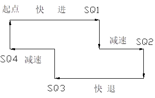
1. According to the following tasks: the reciprocating motion of the worktable is driven by a worm wheel driven by a DC motor, and the speed and direction of the worktable are controlled by a limit switch SQ1-SQ4. The working process of the worktable is: starting, moving to the right, decelerating to the reversal, moving to the left, returning quickly, decelerating to the reversal, and entering the forward working state.
2. requirements:
1. Electrical schematic design, working mode set to automatic cycle, point and move two kinds.
2. PLC ladder diagram design, working mode is set to automatic cycle, point movement, one-cycle cycle and step-by-step four.
3. Necessary electrical protection and interlocking.
4. Act sequentially in automatic circulation.
Procedure Validation Guidance:
(1) Manual mode
Press X20 and press:
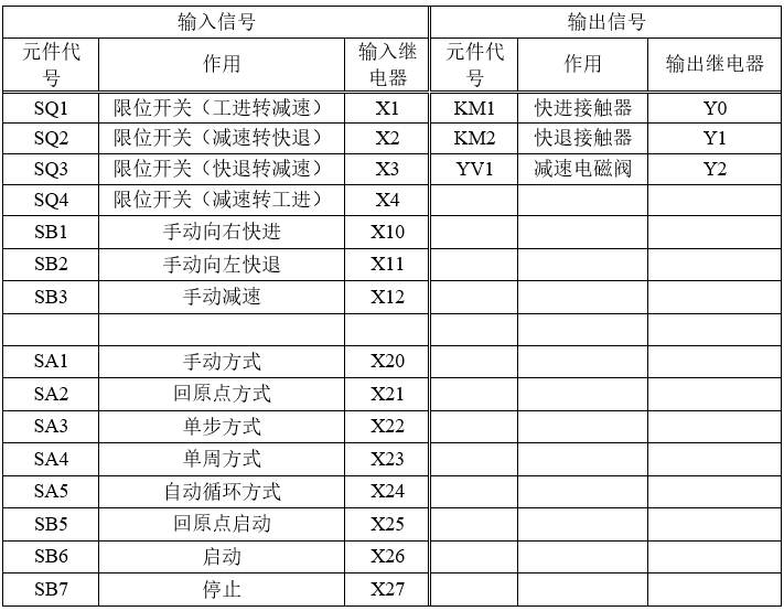
Press the manual right entry button X10 right-shift contactor Y0 and work-in solenoid valve Y2 to get electricity at the same time, and the worktable moves to the right.
Press the manual right entry button X11 right shift contactor Y0 and deceleration solenoid valve Y3 to get power at the same time, and the worktable decelerates to the right.
Press the manual right-hand entry button X12 left-shift contactor Y1 and fast solenoid valve Y4 to get power at the same time, and the worktable retreats to the left quickly.
Press the manual right entry button X13 left shift contactor Y1 and deceleration solenoid valve Y3 to get power at the same time, and the worktable decelerates to the left.
(2) Way of returning to the origin
Press X21 and press it tightly, then press the back-to-origin start button X25: the right-shift contactor Y0 reset, while the left-shift contactor Y1 and the fast solenoid valve Y4 simultaneously get power, and the workbench quickly recedes to the left; when the workbench press to the origin condition button X4, the back-to-origin relay closes and the return to the origin is completed;
Note: Back to the origin is only a transitional function on this map, because the title requirement does not require the way back to the origin.
Automation mode < Includes: one-step mode, one-week mode, continuous mode >
Note: Every time before manual mode is changed to automatic mode, it must go back to the origin.
(1) One-step approach
Press X22 and press tight, press X26 right-shift contactor Y0 to get electricity and work-in solenoid valve Y2 to get electricity, press X1 work-in solenoid valve Y2 to turn off electricity, press X26 decelerate solenoid valve Y3 to get electricity, work-table to-right decelerate decelerate to position to press X2, Y3 to turn off power press X26 right-shift contactor Y0 to reset power loss, left-shift contactor Y1 to get electricity. And the fast solenoid valve Y4 worktable to the left fast retreat fast retreat in place that pressing down X3 Y4 power off pressing X26 decelerating solenoid valve Y3 power to the left deceleration deceleration in place that pressing down X4, Y1 reset power loss, Y3 power loss pressing X26 right shift contactor Y0 position gain electricity and enter solenoid valve Y2 power station to the right repeat
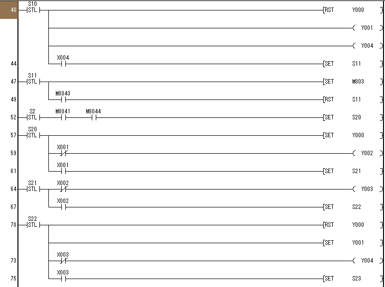
(2) One-week mode
Press X23 and press tight, press X26 right-shift contactor Y0 position to get electricity and work-in solenoid valve Y2 position to get electricity and work-in solenoid valve Y2 position to right work work-in position to press down limit switch X1 (work-in-turn deceleration) work-in solenoid valve Y2 power loss and decelerate solenoid valve Y3 power gain, work-table to right deceleration decelerate to position, that is, press down limit switch X2 (deceleration and fast deceleration) to decelerate solenoid valve Y3 power loss and right shift connection. When the contactor Y0 resets and loses power, the left-shifting contactor Y1 position gains power and the fast solenoid valve Y4 table recedes to the left fast quickly returns to the position and presses down the limit switch X3 fast solenoid valve Y4 loses power and reduces the solenoid valve Y3 gains power at the same time the worktable reduces to the left reduces to the position, that is, the lower limit switch X4 (decelerates to work progress), the left-shifting contact Y1 reset loses power, and Y3 reduces solenoid valve loses power. Electricity Stop.
(3) Continuous mode
Press X23 and press tight, press X26 right-shift contactor Y0 position to get electricity and work-in solenoid valve Y2 position to get electricity and work-in solenoid valve Y2 position to right work work-in position to press down limit switch X1 (work-in-turn deceleration) work-in solenoid valve Y2 power loss and decelerate solenoid valve Y3 power gain, work-table to right deceleration decelerate to position, that is, press down limit switch X2 (deceleration and fast deceleration) to decelerate solenoid valve Y3 power loss and right shift connection. The contactor Y0 resets and loses power at the same time the left-shift contactor Y1 position gains power and the fast solenoid valve Y4 table recedes quickly to the left quickly returns to the position and presses down the limit switch X3 (fast retreat deceleration) the fast solenoid valve Y4 loses power at the same time reduces the solenoid valve Y3 gains power the worktable reduces to the left decelerates to the position, that is, the lower limit switch X4 (deceleration turning into work). The left-shift contactor Y1 resets and loses power, and Y3 reduces solenoid Loss of electricity Right-shift contactor Y0 position to get electricity and work-in solenoid valve Y2 work-table to right-work (next cycle).
Whenever you press X27, it will stop.